The X-Scope
A 12.375" f4.5 Newtonian
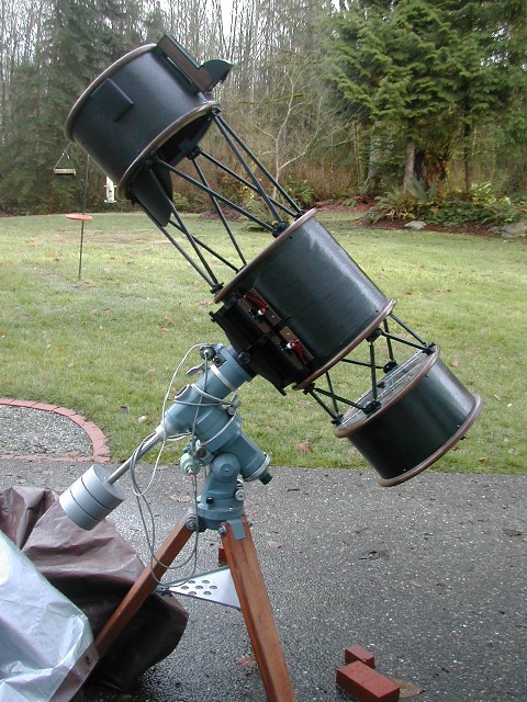
The X-Scope is a 12.25" F4.5 Newtonian. I ground, polished, and figured the mirror, constructed the mirror cell, and fabricated the truss and tube assembly. I purchased the focuser and secondary and I made the secondary holder and spider. First light was December of 2004, approximately 8 months behind schedule.
The scope is mounted on my existing Takahashi NJP160 mount. While the mount is capable of carrying quite a bit of weight, in order to make the rather large scope portable and easy to manage, as well as to avoid wear and tear on the mount, I used lightness as a key design center. Since the scope is to be largely used for CCD imaging, stability is key so rigid, thermally stable materials were used.
The mirror is made from a 12+" BVC blank from ASM. BVC is a relatively inexpensive, laminated product with reportedly excellent thermal stability. It is also very soft and easy to grind and takes a good polish. I have only ever ground one 6" mirror before (in 1988) and that was with considerable help. This is one area I considered to be high risk, but with the help of many kind people, I made it through.
The tube is a tube and truss affair made from Carbon fiber composites and walnut. I had never worked with carbon fiber and had done precious little fiberglass work when I started the project. This was another risk area, but I got it done - not particularly well - but done.
Details on the various stages of development of this scope are accessible through the links below.
The Design
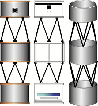
The rough plan for the design of the scope structure - at least as it stands for now. Note the segmented design. This allows for free air movement, light weight, and portability. But it complicates the construction. The bars seen in the center section are intended to tie the trusses together through the middle to make for less stress and flex on the center tube section.
Current thinking is to have it attach to the mount with a dovetail plate affixed to the central tube section. I am considering doing a sort of harness/cage for the central section to allow the tube to rotate for convenience at the eypiece.
The mirror is a 12.375" mirror with a radius of curvature of 111.2". The actual clear area of the mirror is 12.125 so the f ratio comes out to just under 4.6. The tube diameter is 15" and the overall length will be approximately 54".
The mirror cell and secondary holder and spider will all be home made, while the focuser will be a JMI motorized Crayford. Eventually, budget permitting, I hope to add a Robofocus unit as well.
UPDATE: Reality has set in as I actually build this thing. What I have ended up with is a short mirror box, a long central section and a short top end. The center is only about 8" from the mirror box to allow the tube assembly to at least roughly balance. Also, the carbon cloth tube is extremely rigid - especially with the walnut end rings in place - so I haven't gone ahead with the extra supports through the center section. If need be they can be added later. The mirror box weighs about 13 lbs which makes balance an issue. I may need counterweights on the opposite end.
UPDATE 2: Finished! Rigidity proved to be no problem and I managed to get the tube to balance at the right point through the application of three 1.5 lb counterweights to the top section. These are removable as needed.
Initial
tube idea
Stage One: Making the mirror
The mirror blank was ordered from ASM Products. I ordered a 12" pre-curved to F5. I later decided to go to F4.5, but it was too late to change the order. The blank arrived packed in styrofoam and in generally good condition with a few small edge chips on the back side. The blank was actually app. 12.375" in diameter with a clear area (minus bevel) of around 12.25". The pre-curved surface was very close to F5 and looks to be ground with 80 grit. There was one major problem with the blank. The blank had a huge wedge to its shape with nearly 1/4" difference in thickness from one side to the other. I complained to the provider and he said it must be because of a tilt that had developed in the furnace - but not to worry about it. Since I was concerned about astigmatism, I chose to grind it parallel. I should have simply returned it and demanded a new blank. I learned two things from the grinding - BVC grinds quickly, and taking off a quarter inch or even soft glass is a LOT of work. I went through all of the 80 grit provided with the kit just to get it parallel. I never got it all the way there, but the residual curve is even and symmetrical across the back and I decided that with proper support, it wouldn't hurt anything.
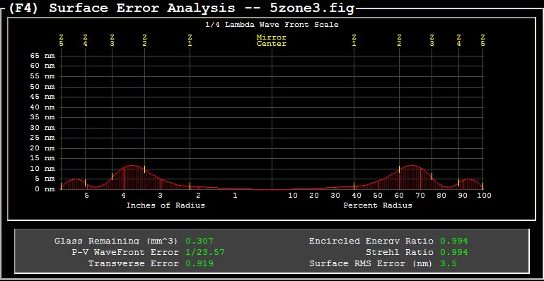
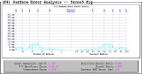
UPDATE: The mirror is now as done as it is going to get for now. The curve is pretty good but the surface is a touch rougher than I had hoped for. Figuring was a long learning experience, and if I had it to do over would go much faster based on not making the same mistakes.
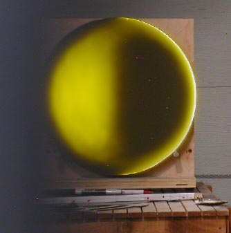
The Final Foucogram
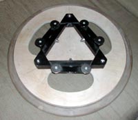
Stage Two: Making the Mirror Cell
The primary mirror cell is a 6 point design to be fabricated from stock aluminum tube and angle along with miscellaneous hardware. The basic design is stolen from here. The proportions specific to this mirror were calculated with Plop. Thanks to the ATM List for helping me understand the Plop output and to realize that I didn't need more than 6 points of support.
Stage Three: Making the Tube
Tube sections are made from carbon fiber using a three-layer construction (two layers of carbon cloth over a core material - Baltek matl). They are very stiff, strong, lightweight and thermally stable. The three tube sections are connected with carbon fiber trusses and ball and socket joints.
The trusses are 1/2" pultruded carbon fiber tubes with threaded inserts at the ends into which rods with ball ends are inserted. The balls are captured by clamps I designed. Making 16 of these was a real chore.
UPDATE: Due to a screw-up, I actually ended up with four layers - carbon cloth, Baltek mat, carbon cloth, and a final layer of carbon twill.
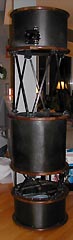
Final Tube Assembly
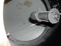
Stage Four: The Top End
I decided to build the diagonal holder and spider myself, but purchased a JMI focuser. The secondary holder is made from sluminum, threaded rod, dowel, and a turned hunk of basswood along with some springs and miscellaneous hardware. The spider is made of guitar strings.
Stage Five: The Cradle and the Final Assembly
The cradle is made of hard maple with walnut for the hinges. So far it appears to work pretty well, though I may decide to replace it with a commercial aluminum rig.
Final assembly went pretty well, with only a couple of glitches. The finished scope balances and rides on my mount with no trouble. Total final weight is around 40 lbs.
Final assembly went well